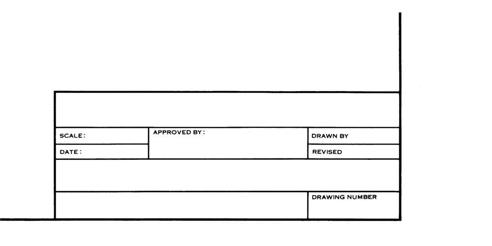


Like a road map these quadrants help to quickly locate specific areas of the drawing. The drawing may have a quadrant system layout with numbers across the bottom of the drawing and letters up the side. The title block will contain information such as drawing title, drawing number, measurement scale, aircraft type, revision status, sheet/page number, approving engineer, and the name of the draftsperson. The typical drawing will have a title block in the lower right hand corner of the drawing. Mastering the use of the drawing tree system will assist you in easily going from the top drawing to a detail part or vice versa. The drawing sheet for a complete aircraft is known as the top drawing and will show major assemblies such as the left wing, right wing, fuselage, and empennage. This drawing tree concept continues until all the assemblies are installed onto their NHA to create a complete aircraft or assembly. This drawing also has a NHA number that correlates to a larger assembly. The NHA drawing shows the assembly or installation of that detail part on the NHA. Once the part is fabricated and identified on the drawing, a next higher assembly (NHA) number is noted. In the drawing title block (which is explained later) for a detail part, a part number is given.

#Blueprint title block with material list for size a series
The drawing treeĪ drawing tree is a system used to locate a specific part or assembly on a series of drawings. Today, drawings may be accessed through web-based systems directly from manufacturers, which ensure the correct revision is used. As an example, heat treat condition or material thickness may have changed from one aircraft to another during production. Also you need to ensure that any amendments noted on the drawing will be applied if applicable. Many aircraft have had long production runs and it’s essential the correct aircraft affectivity is applied to the correct information in the drawing. Typically, aircraft production line numbers are used for affectivity. When using a drawing it is essential the correct affectivity and latest revision to the drawing is utilized. Production drawings used during new manufacture of aircraft and components are sometimes broken down into three different groupings:ĭetail drawings which provide information for single parts, assembly drawings which show two or more parts joined together, and installation drawings which provide information regarding the component/assembly’s location on the aircraft. Types of drawingsĭrawings can be found in many documents like service bulletins, maintenance and structural repair manuals, engineering instructions, and supplemental type certificate (STC) installation instructions. For consistency this article will use the word drawing. Those traditional methods have given way to more modern methods - yet the term “blueprint” is still used today. The aircraft maintenance technician, AMT, must be able to interpret this graphic, determine drawing orientation, the correct drawing affectivity and revision status, and all of the applicable note information.īefore we get started, when drawings were first reproduced in the mid 1800s, early technology would produce a document having a blue background with white lines and writing. The basic purpose of the blueprint is to describe parts and repairs in a graphical fashion and provide a host of design information to the end user regarding dimensions, processes, specifications, tolerances, and more. In the world of aircraft maintenance and construction, blueprints are regularly used to perform a variety of tasks.


 0 kommentar(er)
